Tag Archives: JCMA-733

Replacement of OpAmp (CA3030A) in ORTEC 490J/490JA AMP SCA

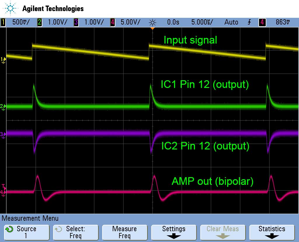
Main OPAMPs (IC1 and IC2) might be damaged if the output voltage of IC1 or IC2 differs from a typical value in the manual. Furthermore, you can observe signals around OPAMPs.

Typical waveforms of 490J/490JA.

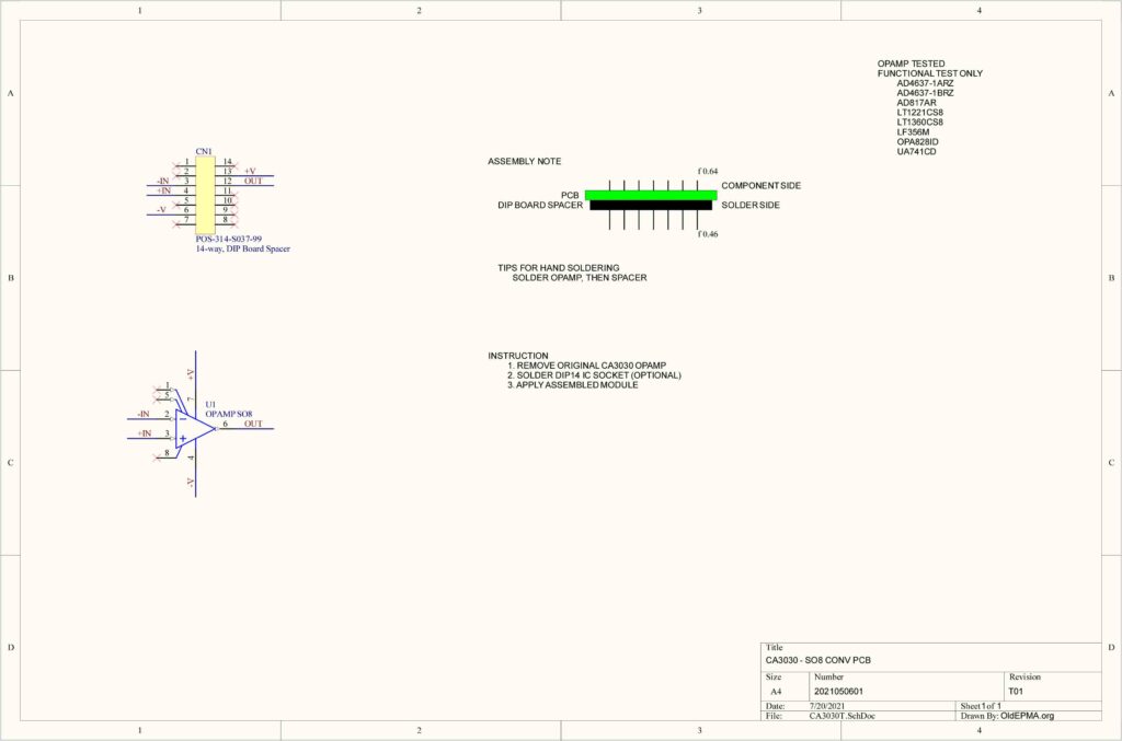
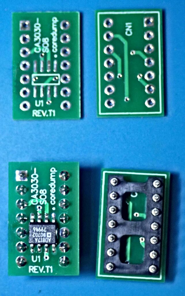
CA3030A has been discontinued, and it is not easy to obtain it. CA3030A can be electronically replaced with a modern OPAMP, keeping compensation pins unconnected. However, its pin configuration differs from that of a modern single OPAMP. A TO-99 metal might be usable for replacement, but a TO-99 package is also uncommon now. Therefore, I made the conversion PCB to use the standard 8-lead SOIC package OPAMP.

CA3030A to SO8 OpAmp conversion PCB.
Schematic

I soldered IC sockets. Therefore, the conversion module is replaceable.

PDP-11/LSI-11 maintenance

A failure module in the PDP-11/LSI-11 unit makes the system unbootable.

Media

The first step is to check the disk media, floppy disk, or hard disk drive. If you have a stock, please try to replace the media.

Disk controller

The system cannot boot when a disk controller is damaged. If you have both floppy and hard drives, please try to boot from one of them. Please note that the jumper setting of a disk controller and MXV11-A module must be set correctly. DEC module, RLV11, RLV12, RXV11, and RXV21 can be tested using the XXDP. As far as I know, third party modules, DSD4140 and BD-05 are strong enough, and I have never seen a broken module.

The RLV12 RL02 disk controller has several major modes of failure.

(1) VCO

The simple one is the drift of the C65 trimmer capacitor. When the VRLBC0 diagnostic gives many data errors, please try to readjust it. The XXDP RLV12 diskless controller test helps readjustment. Also, E135, 74S124, is sometimes damaged.

(Receiver/Transceiver)

The next one is the damage of transceiver/receiver ICs (75113 and 75107B). If both +5V and -5V supplies are OK, please replace them.

(-5V supply)

Yet another problem related to the transceiver and receiver is the failure of the -5V power supply. RLV12 generates -10V from +12V supply and, then, generates -5V using LM360H.

(Sequencer PROM)

The data in a PROM, E20, E21, E22 (82S171), was sometimes broken. You need to replace the broken PROM with correct data. Only limited ROM writers support SIGNETICS/Philips fused PROM (e.g., TopMAX II). (Similar problem may occur in the VACUUM CONT of the JXA-8800/8900 EPMA. They use SIGNETICS fused PLDs.

(Serious damage)

The last problem makes XXDP give MAINTENANCE MODE SEQUENCER ERROR. I have no idea for reason and solution.

Memory module

A failure of DRAM IC on the MSV11-D module also causes the unbootable problem. If you have another MSV11-D module, please try to replace it. The XXDP memory test helps to identify damaged DRAM IC. The address and data give information on the bank and data bit, respectively.
Unstable electron optical system

When you get an unstable beam current, please check the
three components: +80V 1.5A, +75V 7.5A, and AL-02J in the EOS unit.

+80V 1.5A and +75V 7.5A (HV and CL/OL supplies)

The first step is to check the output voltage between check terminals. If the output voltage is incorrect, adjust it by VR1. Also, if the output voltage is unstable, you need to repair the PSS module. The easiest way is to replace all electronic parts on the PCB. You need to use 1/2W or grater registers instead of the original 1/4W registers when replacing the PSS components. The simulation shows the power consumption of those registers is more than 300 mW.


AL-02J (ALIGN coils and STIGMATOR)

I guess that insufficient thermal design may damage transistors on the AL-02 module. If this module’s output is unstable, you can replace transistors mounted on the heatsink (TO-220 package). Please apply high-quality thermal grease.

RLV12 RL01/RL02 Controller damage

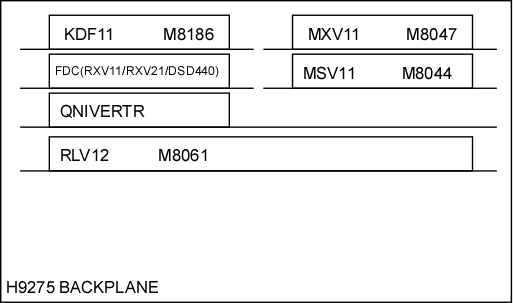
Some JCXA-733/JCMA-733 were shipped with the DEC RLV12 RL01/RL02 controller and RL drives. I saw many damaged the RLV12 installed in JCXA-733/JCMA-733 systems. Once the RLV12 is crashed, it is impossible to access any RL drive. The ZRLBC0 diagnostic program shows the MAINTENACE SEQUENCE failure. As far as I remember, all damaged RLV12 was located above the QNIVERTER. So, I guess the damage is caused by the order of modules in the Q-bus backplane.

Bandade

I placed the RLV12 controller bellow the QNIVERTER as showed in the figure.

[MOD][FIX] 35-DMA read error

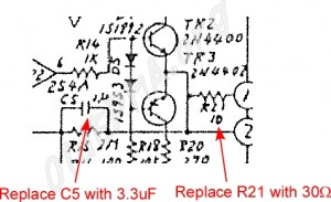
The 35-DMA unit, digital micro ammeter, sometimes causes read error and read value becomes 0. That is, the MA register sometimes becomes 0 after executing the L DMA command. The +5V line near the Tr 14 sometimes drops its voltage when the PRINT ADVANCE signal turns into active. Then, the PRINT ADVANCE signal apparently becomes active again when the voltage drop happens.


Two capacitors, connected to the PRINT ADVANCE signal solve this problem.

[MOD] fix timing problem of 35-DMA

[MOD] Improve safety of SMD

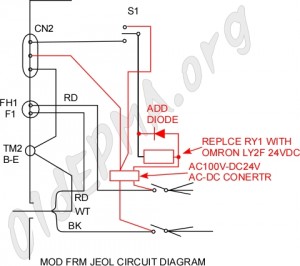
The power of the stepping motor driver (SMD) is controled by the host computer via the cable from CN2 to SGMD2 (STAGE) or SPMD2 (spectrometer).


AC100V is applied to this cable, and I think it is danger, especially when the cable and/or relay on the OCX module are damaged.


The following modification applied DC24V instead of AC100V to control the power of the SMD unit.


733-SMD-mod


The AC-DC converter generates DC24V and it is applied to control the DC24V relay, replacing original AC100V relay.


I believe this improves safety.

JEOL stage gear head repairment

Degration of the gear head(s) of the stage causes large backlash and makes stage positioning inaccurate. Main problem is wear of the clutch part of the gear head unit. It can be fixed by yourself as the procedure below.

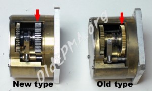
Types of JEOL gear head

There are two types of the JEOL stage gear head.


733-Gearhead-types

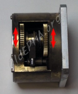
Step 1: Check backlash
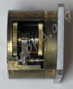
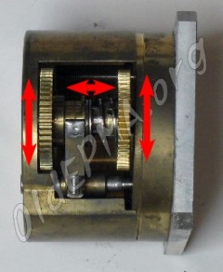
Move gears by hands to check backlash. Gears should not have backlash. If gears have backlash, even small movement, the clutch part needs to be maintained.
Check gears movement
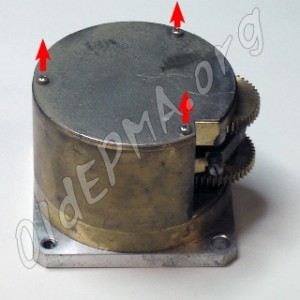
Step 2: Remove the cover
Remove three screws and the cover.
733-Gearhead-Step1
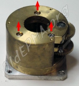
Step 3: Disassemble
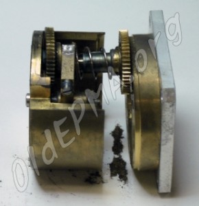
Remove three screws and disassemble the gear head.
733-Gearhead-Step2
733-Gearhead-Step3
Step 4: Cleaning
Clean up all parts using acseton with ultrasonic cleaner.
Step 5: Fix clutch (1)
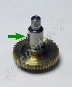
Apply small amount of epoxy resin adhesive to the cluch pin.
733-Gearhead-Step5
Step 6: Fix clutch (2)
Insert the gear and remove it to put small amount of epoxy resin adhesive on the clutch slit. Then, wait.
733-Gearhead-Step7
Step 7: Adjust clutch
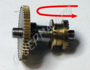
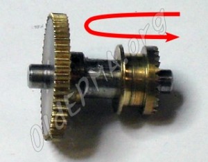
Insert and remove the gear to adjust movement of the clutch system.
733-Gearhead-Step6
Step 8: Assemble
Assemble the gear head unit, applying suitable grease.
733-Gearhead-Step9
Step 9: Check
Check movement of gears and the clutch.
733-Gearhead-FinalCheck